However it can be increased to 8m depending on the size of the pumps to be housed below the pipe rack. Therefore in order to provide for a nominal unbalance of friction forces acting on a pipe support a resultant longitudinal friction force equal to 75 of the total pipe weight or 30 of any one or more lines known to act simultaneously in the same direction whichever is larger is assumed for pipe rack design.
Pipe Rack And Pipe Track Design And Engineering
Most of the data has started arriving.
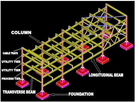
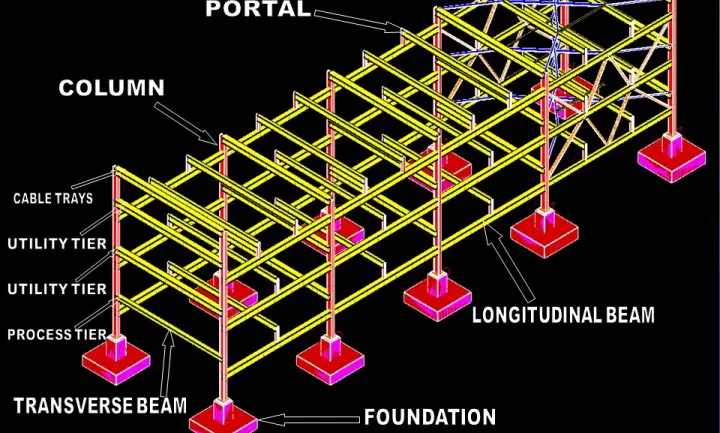
. Intermediate steel is provided in tranverse direction to similar levels. All the information provided by the sturcutral engineer regarding the pipe rack foundations are shown in the following figure and design data section and will serve as input for foundation design. Where consideration of uplift or system stability due to wind or seismic occurrences is required use 60 of the design gravity loads as an all pipes empty load condition.
The width of the rack shall be 6m 8m or 10m for single bay and 12m 16m or 20m for double bay having 4 tiers maximum. There are several ways to determine the width of a pipe rack. A few slight variations from ASCE 7-05 are recommended.
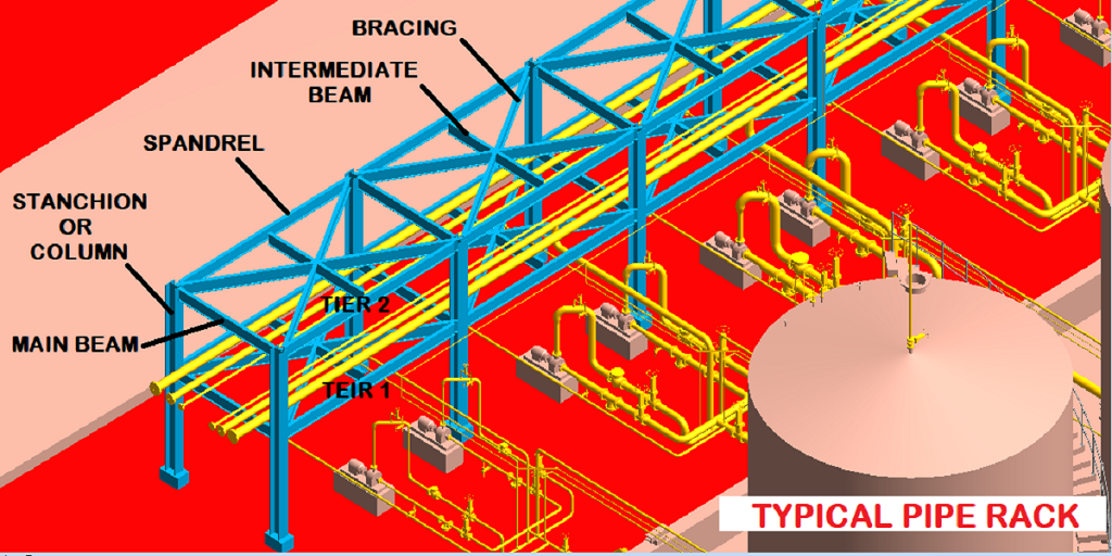
This is usually done during the plot plan development by creating a piping transposition drawing from PIDs and a preliminary equipment layout. It covers general design philosophy and requirements to be used in the analysis and design of pipe racks. This paper summarizes the building code and industry practice design criteria design loads and other design consideration for pipe racks.
If no anchor bay provided Anchors are distributed throught rack. In general spacing between pipe rack portals or bays shall be taken as 6m. This design guide defines the minimum requirements for the analysis and design of pipe racks in process industry facilities.
Pipe Rack Cable Tray Loads. 19 rows Thermla expansion at bends branches taken into consideration for pipe spacing. Pile caps are connected by a foundation slab of 30 m wideThe pipe layersELs 104500 107500 and 110250.
Anchors in pipes at the anchor bay if such bay is provided. Push the ends together to see where the deflection goes and what bends the most. Calculating loads on the pipe racksYour trainer proceeds step by step through the process of modelling columns beams stringers bracingapplying dead loads product loads thermal loads wind loadsNext he proceeds further on how to assign the properties to the structural steel members assigning the releases.
Students will be able to model analyze and design the Pipe Rack in STAAD Pro They will be able to understand how the steel structures are designed. Conservative loads are to be provided. The width of the rack shall be 6 m 8 m or 10 m for single bay and 12 m 16 m or 20 m for double bay having 4 tiers maximum.
Horizontal Deflection dh Check. Orificemeter runs are near the columns for access by portable ladder. Rack loading for final member checking after 60 model.
Operating dead load D o. Small pipes should be grouped together to simplify support design. P W - s x p x d s Spacing of pipe rack bent p pipe weight considered kPa d pipe diameter W pipe concentrated load.
From above calculations 075 X Vc. Pipe racks are structures in petrochemical chemical and power plants that are designed to support pipes power cables and instrument cable traysThe design requirements found in the US building codes are not clear on how they have to be applied to pipe racksThis course summarizes the US design code requirements and industry practice design criteria. Criteria presented herein pertain to loads load combinations allowable stresses and superstructure and foundation design.
A transposition drawing takes the. Width of Pipe rack. Several industry references exist to help the designer apply the intent of the code and follow expected engineering practices.
Bend it into the shape of your pipe configuration and set it down on the desk. In this case the E-W pipe rack height will be 12 from grade and the N-S pipe rack height will be 15 from grade. Dead loads for cable trays on pipe racks shall be estimated as follows unless actual load information is available and requires otherwise.
The operating earthquake load Eo is developed based on the operating dead load as part of the effective seismic weight. Make a close-to-scale model of your pipe configuration using that piece of copper wire. Loads to be provided based on actual analysis.
Dh allowed H 200 Where L horizontal span length of the structure member H height of structure member column The following tables present summary of the results. Check that 075 X Vc Vux where Vux is the shear force for the critical load cases at a distance deff from the face of the column caused by bending about the X axis. 453 Location Locating small pipes between large pipes shall be avoided especially when the large lines are hot.
Pipe racks are typically considered non-building structures therefore seismic design should be carried out in accordance with ASCE 7-05 Chapter 15. The structural adequacy of the subject Legibil 8Wc ity evaluated and peydfor aUe 9305280306 930522 PDR ADOCK 05000390 Signature p A PDR C Microfilm and store calculations in RIMS Service Center. Non-building structures pipe racks support design.
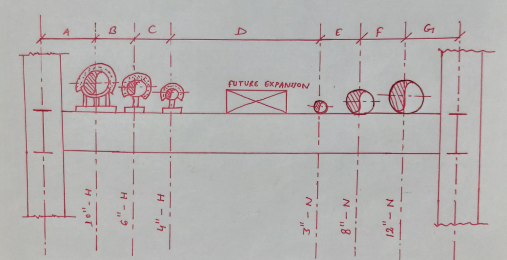
Up to 10 cash back You will start with the absolute basics ie. Rack loading for member sizing after 30 model review. Heaviest lines should be located furthest from centre of the rack.
Dv allowed L 240 2. Vertical deflection dv Check. Critical load case for Vux is.
Lines requiring thermal loops are near the edge of rack. Case study focuses on the design of pipe rack foundations using the engineering software program spMats. Document design calculations for pipe support referenced in calculations title.
Learn Modelling Analyze and Design Pipe Racks in STAAD Pro as per AISC 360. Download PDF - Design Calculation Report - Pipe Rack - And Foundation eljq1w5q0541. Because of poor soil conditions at the site and tower height significant.
Piping design places the lines over the rack based on preliminary PID. TOS EL 108250 and 103250RC column supported on a pile cap modelled as a spring support. A uniformly distributed dead load of 20 psf 10 kPa for a single level of cable trays and 40 psf 19 kPa for a double level of cable trays.
Civil Engineering Structural Steel Design of Pipe Racks. Rack loads are provided mostly based on assumptionexperience. However pump sizes and installation of pumps below pipe rack may need more increased to 8m.
A good desktop modeling tool is a piece of thick copper wire. OR1ONiAL This calculation verifies pipe support. The spacing between pipe rack portals shall be taken as 6m in general.
Distance along X to design for shear Dx.
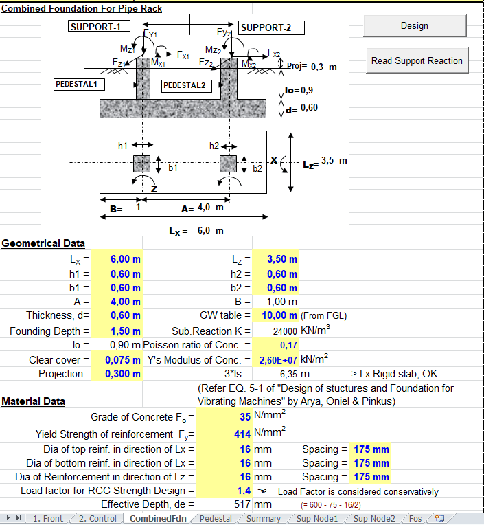
Combined Foundation For Pipe Rack Spreadsheet

Steel Frame Pipe Rack Tutorials Computers And Structures Inc Technical Knowledge Base

Design Of Pipe Rack Layout Considerations
Pipe Rack Design And Calculations Make Piping Easy
Pipe Rack Design And Calculations Make Piping Easy
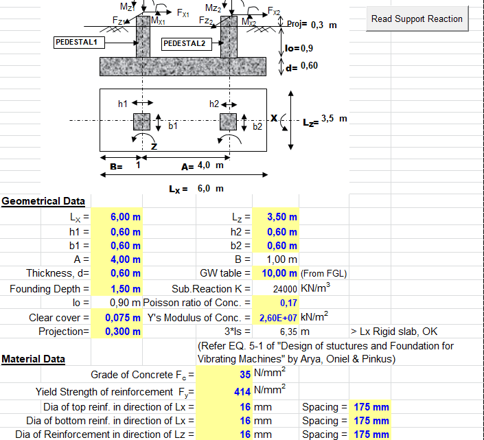
Combined Foundation For Pipe Rack Spreadsheet

Steel Frame Pipe Rack Tutorials Computers And Structures Inc Technical Knowledge Base
Cara Membuat Pipe Rack Yang Baik Teknokal Energi Bersinar
0 comments
Post a Comment